
1. Executive Summary & Semantic Architecture for Solar Power Substation Transformers
As utility-scale photovoltaic (PV) power plants scale from hundreds of megawatts (MW) to multi-gigawatt (GW) capacities, the electrical infrastructure linking solar arrays to high-voltage transmission grids faces unprecedented operational stresses. At the heart of this grid connection lies the Solar Power Substation Transformer (also known as an Inverter-Duty Step-Up Transformer or Solar PV Transformer Station).
Unlike standard utility distribution transformers that operate under stable 50/60 Hz sinusoidal loads with predictable power flow, solar substation transformers are subject to unique, harsh duty cycles: multi-winding high-frequency inverter inputs, severe harmonic distortion (THD), solar irradiance intermittency causing daily thermal cycling, continuous DC bias currents, and aggressive environmental ambient extremes in desert solar parks.
Semantic Search & Information Gain Highlight
Why generic power transformers fail in solar farms: Traditional transformer designs calculate thermal rise based on linear 50Hz sinusoidal load curves. Solar inverter step-up transformers experience non-sinusoidal voltage waveforms with high total harmonic distortion (THD), high frequency pulse-width modulation (PWM) ripple, and reverse power flow during grid feedback. Without electrostatic shielding between windings, K-factor rated core-coil assemblies, and low-loss magnetic steel, standard transformers suffer premature insulation breakdown, localized hot-spot overheating, and excessive stray load losses.
Federal Power Transformers LLC (FPT), headquartered in ICAD 1, Abu Dhabi, UAE, manufactures state-of-the-art oil-immersed and dry-type solar substation transformers up to 100 MVA, 132kV class. Engineered in accordance with international standards including IEC 60076-16 (particular requirements for wind turbine and solar application transformers), ANSI C57.12.00, and BS-171, our solar substations deliver uncompromised reliability across global megawatt-scale solar installations.
2. Technical Product Portfolio & Engineering Specifications
Global procurement managers and EPC engineers must select exact transformer topologies based on inverter cluster size, system DC voltage (1000V DC vs 1500V DC), and grid interconnection voltages. Federal Power Transformers provides three core solar substation configurations tailored for modern solar power plants:

1500V DC Multi-Winding Solar Step-Up Transformers
Specifically designed to connect two, three, or four central solar inverters to a single transformer tank. Features galvanically isolated low-voltage (LV) windings (e.g., 3-winding or 4-winding setups) to prevent circulating currents between inverters while stepping up voltage to 11kV, 22kV, 33kV, or 34.5kV medium-voltage collector grids.
Containerized & Skid-Mounted Solar Compact Substations
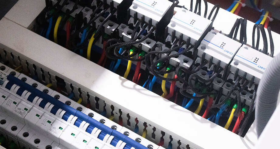
Fully integrated plug-and-play outdoor substations combining liquid-filled or dry-type solar step-up transformers, medium-voltage (MV) gas-insulated switchgear (GIS/SF6-free), low-voltage (LV) inverter interfaces, auxiliary transformers, and smart remote terminal units (RTU) housed inside heavy-gauge galvanised steel enclosures.
132kV Main Solar Substation Power Transformers (up to 100 MVA)
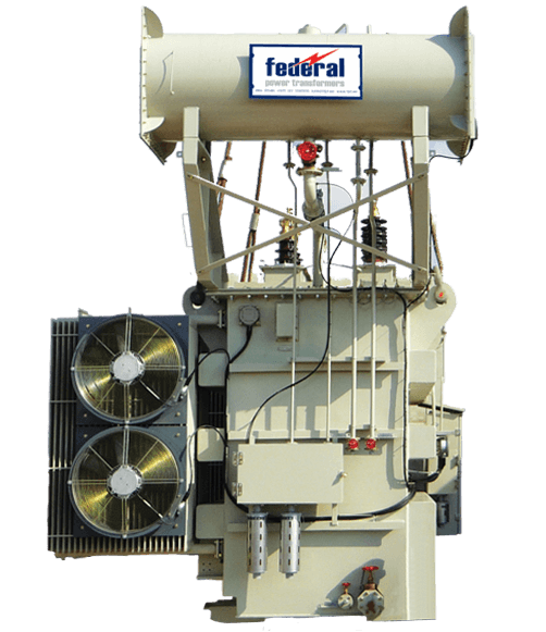
Heavy-duty utility-grade power transformers installed at the solar plant central substation step-up stage. Converts 33kV collector busbar voltages directly into 110kV/132kV transmission grids. Equipped with On-Load Tap Changers (OLTC), online dissolved gas monitoring, and C5-M anti-corrosion protection.
Technical Performance Matrix: Federal Power Solar Transformers
| Technical Parameter | Medium Voltage Solar Step-Up (Inverter Duty) | Utility Interconnection Power Transformer |
|---|---|---|
| Power Rating (Capacity) | 1.0 MVA to 12.5 MVA | 10 MVA to 100 MVA |
| Primary / High Voltage (HV) | 11kV, 22kV, 33kV, 34.5kV (Up to 36kV) | 66kV, 110kV, 132kV Class |
| Secondary / Low Voltage (LV) | 400V, 600V, 630V, 690V, 800V AC (Multi-LV Setup) | 11kV, 22kV, 33kV, 34.5kV |
| Winding Configuration | Dual-Winding, 3-Winding (Dy11y11), 4-Winding (Dy11y11y11) | YNd11, YNyn0d11 with Vector Group Customization |
| Dielectric Fluid Medium | Mineral Oil (IEC 60296) / Synthetic & Natural Ester (IEC 61099) | High-Grade Inhibited Mineral Oil / Synthetic Ester Fluid |
| Insulation Class / Temp Rise | Class A / 55°C or 60°C Top Oil, 65°C Winding Rise | Class A / Customized for Ambient Temperatures up to 55°C |
| Harmonic Mitigation (K-Factor) | K-4, K-9, K-13, K-20 with Electrostatic Grounded Shielding | Designed for System Harmonic Limits (IEEE 519) |
| Cooling System | ONAN / ONAF (Corrugated Tank or Detachable Radiators) | ONAN / ONAF / OFAF |
| Corrosion & Enclosure Rating | ISO 12944 C5-M Heavy Industrial/Marine, IP55/IP65 | ISO 12944 C5-M Heavy Industrial/Marine Outdoor |
3. Critical Engineering Considerations for Desert Solar Park Installations
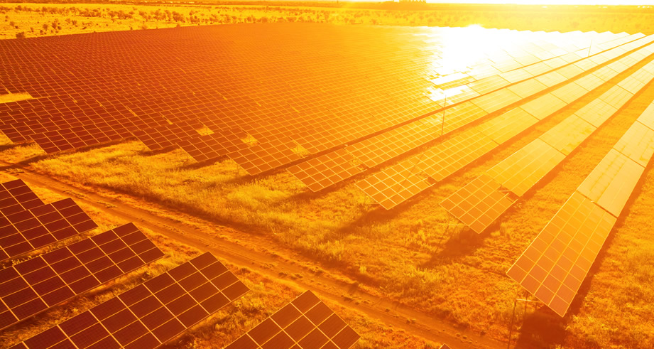
Over 60% of world-scale solar PV developments are located in arid, desert regions (such as the Middle East, North Africa, Australia, and Atacama) characterized by extreme solar irradiance. Engineering a solar power substation transformer for these environments requires specific design countermeasures:
3.1 Thermal Management Under High Ambient Temperatures (50°C to 55°C)
Standard transformer ratings assume a peak ambient temperature of 40°C and a 24-hour average of 30°C. In desert solar installations, daytime ambient temperatures routinely reach 50°C–55°C, amplified by intense direct solar radiation on the transformer tank surfaces. If left unadjusted, insulation ageing doubles for every 6°C temperature increase above the thermal limit.
- Reduced Winding Temperature Rise: FPT designs solar transformers with restricted winding temperature rise (e.g., 50°C or 55°C instead of standard 65°C) to compensate for elevated ambient baselines.
- Solar Radiation Shielding & Sunshades: Tanks can be equipped with detachable radiation heat shields to minimize direct solar flux absorption.
- Thermally Enhanced Insulating Oils: Utilizing synthetic and natural ester fluids with superior thermal stability and higher flash points (>300°C) compared to conventional mineral oil (>140°C).
3.2 Mitigating Inverter Harmonics & DC Magnetization Bias
Grid-tied solar inverters rely on High-Frequency Insulated Gate Bipolar Transistors (IGBTs). Although modern inverters incorporate advanced filtering, residual pulse-width modulation (PWM) harmonics and minor DC offset currents inevitably flow into the low-voltage transformer windings.
DC currents cause unsymmetrical flux shifting in the transformer's magnetic core, leading to core saturation, increased audible noise, elevated eddy current losses, and sharp increases in idle current. To resolve this, FPT incorporates:
- Electrostatic Shielding: A grounded copper shield placed between the HV and LV windings to bypass high-frequency common-mode capacitive noise directly to earth.
- Flux Density De-rating: Designing the core magnetic operating point significantly below the saturation knee point (typically $\le 1.65$ Tesla) to accommodate DC bias without saturating core laminations.
- K-Factor rated Winding Conductors: Utilizing transposed strip conductors or Continuously Transposed Cable (CTC) to minimize skin effect and eddy current heating caused by higher-order harmonics ($h_5, h_7, h_{11}, h_{13}$).
3.3 Sandstorm Resistance, Dust Ingress & C5-M Anti-Corrosion
Fine silica sand and airborne salts present in desert environments create conductive dust layers across transformer bushings and radiational cooling fins. FPT protects its solar substation transformers through:
- High Creepage Distance Bushings: Specifying anti-fog porcelain or composite silicone rubber bushings with creepage distances exceeding 31mm/kV or 40mm/kV to prevent flashovers.
- Hermetically Sealed Bushing Enclosures: Cable boxes rated to IP65 with double gasket seals preventing fine dust ingress.
- C5-M Surface Treatment: Tank surfaces undergo shot-blasting to SA 2.5 followed by a multi-layer epoxy and polyurethane coating system conforming to ISO 12944 C5-M (Very High Marine / Coastal Industrial Corrosivity).
4. Future Procurement Trends & Industry Developments (2025–2030)
The global solar energy ecosystem is shifting rapidly toward higher integration density, digitized grid management, and net-zero manufacturing lifecycles. Global procurement leaders must align their equipment specifications with the following multi-year industry trajectories:
4.1 Integration with Battery Energy Storage Systems (BESS)
Modern solar farms are increasingly deployed as hybrid PV-plus-BESS power plants. Substation transformers must now handle bidirectional power flow—stepping up solar power to the grid during peak sunshine hours and stepping down grid or solar power to charge battery energy storage banks during low-tariff or excess-generation windows.
FPT's dual-function BESS-Solar Substation Transformers feature reinforced mechanical clamping on core-coil assemblies to endure severe short-circuit electromagnetic forces resulting from rapid phase-angle flips and frequent microgrid islanding transitions.
4.2 Transition to Biodegradable Ester Fluids (Natural & Synthetic)
Environmental social governance (ESG) mandates are driving global buyers away from conventional mineral oils toward natural ester (vegetable-based) and synthetic ester insulating fluids (such as FR3 or MIDEL 7131):

- Fire Safety (K-Class Fluids): Ester fluids have fire points above 300°C, eliminating the need for expensive deluge water spray systems and fire-wall barriers between close-coupled containerized substations.
- 100% Biodegradability: Readily biodegradable within 28 days (OECD 301), preventing soil and groundwater contamination in the event of an accidental spill.
- Extended Insulation Life: Ester fluids absorb water moisture out of the cellulose paper insulation, delaying paper degradation and effectively doubling transformer asset life expectancy under heavy solar thermal cycles.
4.3 Smart Transformer Telemetry & AI-Driven Predictive Maintenance
Modern utility-scale solar farms span thousands of hectares, making manual physical inspection impractical. Procurement specifications now mandate Smart Substation Transformers equipped with digital sensor arrays integrated into SCADA and AI-based asset health management platforms:
- Fiber-optic direct winding hot-spot temperature sensors (real-time thermal tracking).
- Online Dissolved Gas Analysis (DGA) for early detection of hydrogen ($H_2$), acetylene ($C_2H_2$), and carbon monoxide ($CO$) generation.
- Continuous moisture-in-oil and bushing capacitance monitoring.
- Automated smart breathers with self-regenerating silica gel drying cycles.
5. Why Leading Global EPCs Partner with Federal Power Transformers LLC
Federal Power Transformers LLC (FPT) represents the pinnacle of Middle Eastern manufacturing excellence backed by global quality standards. Established in 2006 in Abu Dhabi, UAE, FPT operates under the Federal Electric group umbrella, delivering high-reliability power solutions worldwide.
ICAD 1 Abu Dhabi State-of-the-Art Facility
Located in Mussafah, Abu Dhabi, our facility spans thousands of square meters featuring dust-free climate-controlled winding bays, automated core cutting, and advanced vacuum drying / oil impregnation chambers.
ISO Certified Quality & EHS Management
Fully certified in ISO 9001:2015 (Quality), ISO 14001:2015 (Environmental), and ISO 45001:2018 (Occupational Health & Safety). Operating under our uncompromising "Target Zero" safety and defect policy.
Precision AutoCAD & Inventor Core Engineering
Every solar transformer core-coil structure undergoes 3D Finite Element Analysis (FEA) magnetic, mechanical short-circuit, and thermal fluid dynamics simulation prior to physical assembly.
In-House High Voltage Testing Laboratory
Equipped for 100% routine testing, full impulse voltage withstand testing, temperature rise tests, dynamic short-circuit withstand validation, and partial discharge measurement per IEC 60076.
Custom Solar Transformer Engineering for Your Grid Connection
Need custom multi-winding voltage ratios, specific vector groups, or containerized solar skid substations? Contact our engineering team in Abu Dhabi for direct technical consultations.
Send an Inquiry6. Frequently Asked Questions (FAQ) for Solar Substation Transformer Procurement
Standard distribution transformers step down steady utility line voltage to end-user levels under linear load profiles. A Solar Inverter Step-Up Transformer receives pulsed, non-sinusoidal AC voltage from solar inverters, steps it up to medium or high voltage collector grids, and must handle severe high-frequency harmonics (THD), DC voltage components, high rate of dv/dt voltage transients, and daily thermal cycling without insulation thermal runaway. Solar transformers also often feature multi-LV winding configurations (e.g., 3-winding or 4-winding) isolated by grounded electrostatic shields.
Multi-winding designs (such as Dy11y11 or Dy11y11y11) allow two, three, or four separate central solar inverters to connect to a single step-up transformer tank. This significantly reduces overall substation footprint, lowers balance-of-plant (BOP) cabling costs, reduces switchgear counts, and minimizes core magnetic idle losses compared to installing individual transformers for each inverter. Galvanic isolation between the low-voltage windings prevents circulating cross-currents between the inverter blocks.
IEC 60076-16 is the dedicated international standard governing "Transformers for Wind Turbine and Solar Power Application." It sets specific guidelines for evaluating additional eddy current losses caused by inverter harmonic spectra, specifies insulation stress testing for high dv/dt inverter switching transients, mandates mechanical strength considerations for frequent thermal loading variations, and defines criteria for multi-winding load sharing.
Ester fluids (such as FR3 natural ester or MIDEL synthetic ester) offer a fire point >300°C (K-class), compared to ~140°C for mineral oil (O-class), classifying them as fire-safe and eliminating expensive deluge water suppression systems. Esters are also 100% biodegradable within 28 days, protecting soil and ground water. Furthermore, ester fluids hold significantly more moisture than mineral oil without sacrificing dielectric strength, extracting moisture from kraft paper insulation and extending total transformer life by up to 200%.
K-Factor quantifies a transformer's ability to operate safely while supplying non-linear harmonic loads. While standard commercial loads use K-1 or K-4, central solar inverters typically require K-9, K-13, or K-20 ratings depending on inverter topology (string inverters vs central inverters), switching frequencies, and total harmonic distortion (THD). Specifying the correct K-Factor ensures conductors and magnetic cores are dimensioned to prevent stray eddy current hot spots.
Production lead times for medium-voltage solar transformers (up to 10 MVA) typically range from 12 to 16 weeks, while 132kV main step-up utility transformers range from 20 to 26 weeks depending on raw material availability and custom design parameters. Factory Acceptance Testing (FAT) takes place at our ICAD 1 laboratory in Abu Dhabi, where clients or third-party inspectors (e.g., SGS, Bureau Veritas, DNV) witness routine tests, temperature rise, switching impulse, and partial discharge measurements.
During peak sunlight, power flows from solar array to grid. At night, solar PV plants enter standby mode, drawing minimal auxiliary power back from the grid for monitoring, tracking motors, and security systems. FPT solar transformers are engineered with ultra-low no-load (core) losses using high-permeability grain-oriented silicon steel (CRGO) or amorphous core metal to minimize 24/7 continuous no-load core energization costs during non-generating night hours.
Initiate Your Solar Substation Procurement Request
Partner with Abu Dhabi's premier transformer manufacturer for reliable, utility-scale power infrastructure engineered for peak solar performance.