
The Definitive Global Procurement & Engineering Guide to Power Distribution Transformers
An in-depth technical analysis covering transformer architecture, Total Cost of Ownership (TCO) optimization formulas, ester dielectric solutions, smart grid IoT integration, and international procurement standards for utility and industrial applications up to 100 MVA, 132kV class.
1. Architectural Anatomy & Engineering Spectrum of Power Distribution Transformers
In modern power systems, Power Distribution Transformers serve as critical electromagnetic nodes, transferring electrical energy between voltage levels while maintaining grid stability, high energy efficiency, and operational safety. Global procurement engineers and utility managers frequently face complex trade-offs between liquid-immersed power units and cast resin dry-type distribution transformers when tailoring infrastructure for utility networks, renewable generation plants, or heavy industrial complexes.
Federal Power Transformers LLC (FPT), headquartered in ICAD 1, Abu Dhabi, engineers transformers operating up to 100 MVA and 132kV class. Designing for these extreme thermal and electrical stresses requires absolute mastery over magnetics, insulation dielectric strength, short-circuit mechanical forces, and fluid dynamics.
Understanding the fundamental distinction between Power Transformers and Distribution Transformers is paramount for accurate procurement specifying:
- Power Transformers (Substation Class): Installed at transmission interconnects or primary step-down substations (ranging from 10 MVA up to 100 MVA, operating at 33kV, 66kV, 115kV, or 132kV). They are optimized for near-continuous full-load duty (90-100% load factor), where maximum efficiency is aligned with full rating.
- Distribution Transformers (Medium-to-Low Voltage): Deployed downstream in distribution networks, commercial complexes, and industrial plants (ranging from 50 kVA to 5 MVA, typically stepping down 33kV, 22kV, or 11kV to 415V/240V). Operating under fluctuating daily demand curves (averaging 40% to 70% load factor), their magnetic core geometry is engineered specifically to minimize continuous no-load core losses ($P_0$).
Technical Information Gain: Core Physics & Materials Science
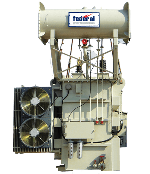
At FPT, core structures are crafted using high-permeability, Cold-Rolled Grain-Oriented (CRGO) silicon steel laminations (grades M0H, M1H, or Domain-Refined Laser-Scribed steel). Utilizing step-lap mitred joints (45-degree angle cutting), core assembly reduces magnetic flux distortion, suppresses third-harmonic generation, and cuts no-load losses by up to 18% compared to traditional butt-lap designs while keeping operational acoustic noise strictly below DEWA and IEC 60076-10 thresholds.
2. High-Performance Product Recommendation Matrix for Global Buyers
Selecting the right transformer configuration depends directly on installation environmental conditions, load profiles, ambient temperatures, and fire safety mandates. Below is a detailed engineering overview of FPT’s core product lines engineered in Abu Dhabi and deployed across global power projects.
Oil-Immersed Power Transformers
Heavy-duty substation units up to 100 MVA, 132kV. Equipped with On-Load Tap Changers (OLTC) or Off-Circuit Tap Changers (OCTC), ONAN/ONAF cooling configurations, and hermetic or conservator sealing systems.
- IEC 60076 & ANSI C57 certified
- High short-circuit withstand capability
- Custom oil conservator with silica gel/maintenance-free breathers
Cast Resin Dry-Type Transformers
Fire-safe, self-extinguishing Class F or H insulated transformers up to 15 MVA, 36kV. Encapsulated in high-vacuum epoxy resin for zero moisture absorption and zero partial discharge (<10 pC).
- Class F1 fire behavior compliance
- Ideal for high-rises, hospitals & data centers
- Maintenance-free non-polluting design
Renewable Energy Transformers
Specially designed step-up transformers for PV solar inverters and wind turbine generators. Multi-winding configurations (dual/triple secondary) engineered to sustain high harmonic distortion.
- K-factor rated for non-linear load harmonics
- Electrostatic shielding between HV & LV windings
- Biodegradable synthetic ester fluid options
Summary Technical Parameter Specifications Matrix
This reference matrix serves global procurement teams standardizing tenders across utility grid expansions, oil & gas concessions, and industrial plants:
| Transformer Type | Rating Range (MVA) | Primary Voltage Class | Cooling Medium | Insulation Class | Target Applications |
|---|---|---|---|---|---|
| Primary Power Transformers | 10 MVA to 100 MVA | up to 132 kV | ONAN / ONAF / OFAF | Class A (105°C) / Ester | Main Transmission Substations, Grid Interconnects |
| Substation Distribution Units | 250 kVA to 5,000 kVA | 11kV / 22kV / 33kV | ONAN / KNAN | Class A or Class K (Ester) | Residential Distribution, Utilities, Commercial Hubs |
| Cast Resin Dry-Type | 100 kVA to 15 MVA | up to 36 kV | AN / AF (Air Natural/Forced) | Class F (155°C) / H (180°C) | Data Centers, High-Rise Towers, Underground Metro |
| Oil & Gas Heavy Industrial | 500 kVA to 30 MVA | 11kV to 33kV | ONAN / ONAF (Corrosion C5-M) | Class A / Synthetic Ester | Offshore Rigs, Refineries, Hazardous Zone 1/2 |
| Skid Mobile Substations | 1 MVA to 25 MVA | 11kV to 132kV | ONAN / ONAF Compact | Hybrid High-Temp Insulation | Emergency Power, Mining, Disaster Recovery |
3. Technical Procurement Guide: Evaluating Transformer Efficiency & TCO
Procuring power distribution transformers strictly based on initial capital expenditure (CAPEX) frequently results in long-term financial loss. Electrical losses accumulating across a 30-year operational lifecycle often exceed the initial purchase price by 200% to 400%. Professional utility procurement mandates evaluating Total Cost of Ownership (TCO) using formal loss capitalization math during tender adjudication.
Where:
• P₀ = No-Load Loss (Core Loss) in kilowatts (kW)
• Pₖ = Load Loss (Copper/Winding Loss at rated current & 75°C/115°C) in kW
• A = Capitalization factor for No-Load Loss ($/kW) [typically $4,000 – $10,000 per kW]
• B = Capitalization factor for Load Loss ($/kW) [typically $1,500 – $4,000 per kW]
Why No-Load Losses ($P_0$) Are Capitalized at a Higher Rate ($A > B$)
No-load losses occur continuously within the hysteresis and eddy currents of the magnetic core whenever the transformer is energized, regardless of whether it is serving 1% or 100% electrical load. Consequently, utilities penalize $P_0$ heavily (higher 'A' factor). In contrast, load losses ($P_k$) vary quadratically with current ($I^2R$) and depend entirely on real-time consumer load demand.
Critical Mechanical & Thermal Verification Criteria
When reviewing factory acceptance testing (FAT) protocols, procurement officers must ensure compliance with three critical physical metrics:
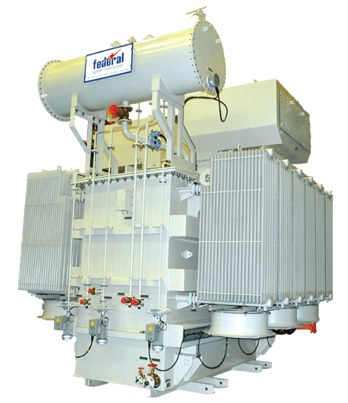
- Short-Circuit Dynamic Withstand Strength: Transformers must sustain extreme electromagnetic forces ($F \propto I_{sc}^2$) during external grid faults. FPT designs utilize high-density pre-compressed pressboard spacers, radial core clamping, and rigid end-ring structures to prevent radial buckling and axial telescoping.
- Thermal Hot-Spot Temperature Limit: Under IEC 60076-2, the top oil temperature rise must not exceed 60K (for mineral oil), and average winding rise must remain under 65K. FPT incorporates directed oil cooling pathways (ODAF/ODAN) to eliminate localized hot-spots that degrade insulation paper (Kraft paper DP value reduction).
- Partial Discharge (PD) Thresholds: For high-voltage liquid units (≥66kV) and all dry-type units, partial discharge levels must remain strictly under 10 pC to guarantee zero microscopic void erosion inside dielectric structures.
4. Future Procurement Trends & Strategic Technology Developments
The global transition toward decentralized renewable grids, urban intensification, and stringent ESG decarbonization mandates is reshaping transformer architecture. Procurement teams planning infrastructure for 2025–2035 must integrate four key technological vectors:
A. Transition to Eco-Friendly Dielectric Ester Fluids
Traditional mineral oils are increasingly being phased out in favor of Natural Esters (vegetable-based oils) and Synthetic Esters (Midel 7131 / FR3). Esters offer transformative benefits:
- High Fire Safety (K-Class): Fire point exceeding 300°C (compared to ~140°C for mineral oil), eliminating the need for expensive fire walls and deluge water spray systems in urban substations.
- Environmental Protection: Readily biodegradable (>99% broken down within 28 days under OECD 301 tests), preventing soil and groundwater contamination in eco-sensitive zones.
- Moisture Absorption & Paper Longevity: Esters consume water molecules generated by cellulose aging, maintaining drier paper insulation and extending transformer operational life by up to 300%.

B. Smart Transformers & Digital Twin IoT Integration
Procurement specifications are shifting from passive static transformers to Smart Connected Assets. Modern power distribution units manufactured by Federal Power Transformers can be optioned with integrated online monitoring suites:
- Online Dissolved Gas Analysis (DGA): Multi-gas sensors continuously measuring hydrogen ($H_2$), acetylene ($C_2H_2$), ethylene ($C_2H_4$), and moisture in oil to detect arcing, corona, and thermal faults weeks before catastrophic failure occurs.
- Fiber-Optic Direct Temperature Sensing: Fiber probes embedded inside winding turns providing real-time direct hot-spot measurement rather than mathematical estimations.
- Smart Asset Health Index (AHI): Algorithms combining DGA, load factors, bushing capacitance, and vibration data via IEC 61850 protocol direct to utility SCADA systems.
C. High Harmonic Withstand for Solar & EV Supercharging Infrastructure
Modern power grids face severe harmonic pollution caused by solar PV inverters, battery storage (BESS) bi-directional converters, and ultra-fast DC electric vehicle charging hubs. Non-linear currents introduce eddy current loss multipliers ($K$-factor). FPT engineers harmonic-duty transformers featuring electrostatic copper shields between windings, transposed conductors (CTC) to minimize skin effect, and oversized neutral conductors designed for 200% rating.
Buyer Intelligence5. Global Procurement FAQ: AI Search Intent & Technical Queries Solved
Below are authoritative responses to the most critical technical and commercial queries submitted by international buyers, EPC contractors, and grid operators:
6. Why Partner with Federal Power Transformers LLC (E-E-A-T Proof)
Federal Power Transformers LLC (FPT), a core business unit of Federal Electric, stands as an industry benchmark for precision transformer engineering across the Middle East, Africa, and international export markets.
Proven Industrial Infrastructure & Capabilities
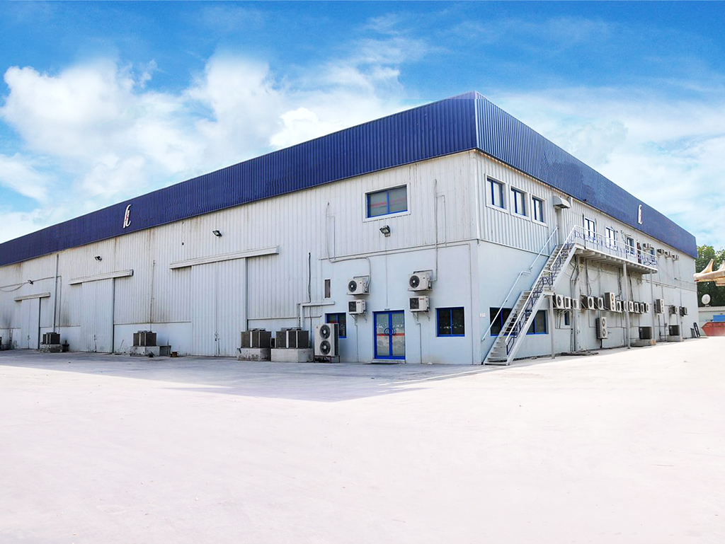
- State-of-the-Art Facility: Situated in Industrial City of Abu Dhabi 1 (ICAD 1, Mussafah), spanning advanced dust-free, climate-controlled winding rooms, automated vacuum drying ovens, and high-vacuum oil impregnation plants.
- Complete Testing Laboratory: Equipped for all Routine Tests, Type Tests, and Special Tests in compliance with IEC 60076, ANSI C57, and BS 171 standards. Testing capabilities include high-voltage lightning impulse withstand (up to 132kV BIL), loss measurement, power frequency withstand, partial discharge measurement, and sound level testing.
- Stringent Quality Approvals: Approved by top regional utilities and energy majors including ADDC, AADC, DEWA, SEWA, OETC, KOC, and ADNOC.
- End-to-End Service Capability: Beyond manufacturing, FPT offers specialized transformer site testing, oil filtration, complete rewinding, and tap-changer overhaul services across the globe.
Commitment to Target Zero & Sustainable Manufacturing
Operating under integrated ISO 9001:2015 (Quality), ISO 14001:2015 (Environmental), and ISO 45001:2018 (Occupational Health & Safety) certifications, Federal Power Transformers enforces a strict Target Zero policy — Zero Injuries, Zero Environmental Incidents, and Zero Non-conforming Deliveries.
Partner with Abu Dhabi's Premier Transformer Manufacturer
Whether you require standard 11kV distribution units or complex 100 MVA, 132kV power transformers engineered for extreme ambient environments, our technical sales team is ready to support your RFQ.
Get a Quote