
Executive Engineering Summary & Information Gain
Modern mega-scale infrastructure—ranging from hyper-scale AI data centers and green hydrogen refining facilities to ultra-high-rise commercial towers—demands unprecedented electrical power density and operating efficiency. Traditional thick-cable bundle installations suffer from excessive magnetic loss, severe voltage drops, labor-intensive trenching, and complex thermal management. High-performance Electrical Busway Systems (also referred to as busbar trunking systems) have emerged as the definitive global standard, offering up to 60% space reduction, zero-halogen fire safety, superior dynamic short-circuit withstand ratings (up to 150 kA Icw), and flexible plug-in tap-off connectivity. This guide provides EPC contractors, utility procurement managers, and consulting engineers with an authoritative roadmap for evaluating, specifying, and procuring optimized electrical busway systems.
1. Understanding Electrical Busway System Architecture
An Electrical Busway System is a prefabricated, enclosed electrical power distribution assembly consisting of copper or aluminum busbars protected by a robust extruded housing. Designed to conduct high continuous electrical currents—typically ranging from 250A up to 6300A in low-voltage applications and up to 24kV in medium-voltage networks—busways deliver engineered power from transformers, generators, and main switchboards to downstream distribution loads.
Unlike conventional multi-core power cabling, which relies on heavy PVC/XLPE insulation sleeves stacked inside cable trays, modern busway systems utilize optimized conductor geometry and direct sandwich insulation. By removing air gaps between conductors, sandwich-type busways drastically reduce loop inductance, minimize voltage drop over extended runs, and accelerate thermal conduction from the inner copper/aluminum conductors to the outer metal enclosure.
2. Recommended Electrical Busway Product Configurations
Selecting the optimal busduct geometry requires matching environmental ingress ratings, ambient temperature profiles, harmonic loads, and structural load constraints. Below are Federal Power Transformers' core product offerings engineered for global commercial, industrial, and utility projects:
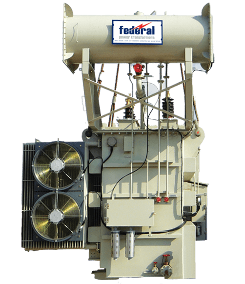 High Ampacity
Compact Sandwich Busway Systems (250A – 6300A)
Engineered with high-grade ETP copper or 99.9% electrical-grade aluminum conductors insulated with 130°C Class B or 155°C Class F polyester/epoxy insulation. Housed in a two-piece extruded aluminum casing for minimal magnetic hysteresis loss.
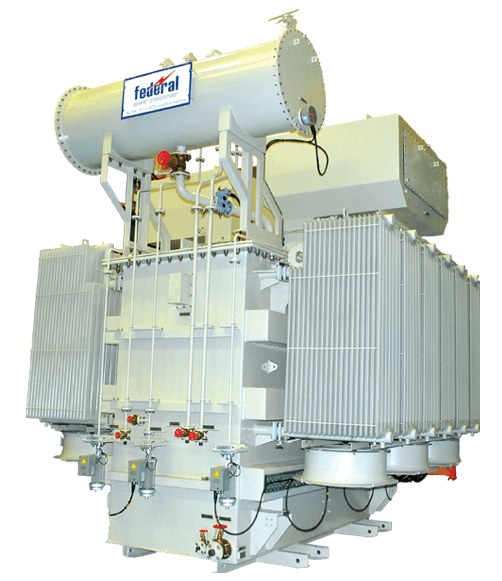 IP68 Outdoor / O&G
IP68 Cast Resin Heavy-Duty Busway Systems
Designed for severe petrochemical, marine, and underground mining environments. Busbars are fully encapsulated in a solid compound of epoxy resin mixed with fine silica sands, offering complete water immersion capability and IK10 mechanical impact protection.
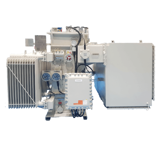 Data Center / Modular
Track & Plug-In Busway Systems for Data Centers
Features continuous open-slot or high-density plug-in access boxes allowing hot-swappable tap-off unit installations without de-energizing the main feed. Integrates native RS-485 Modbus and Modbus TCP energy metering for rack-level power monitoring.
Technical Feature Matrix: Busway Systems vs Traditional Cabling
To assist project engineers in total cost of ownership (TCO) and feasibility studies, the following comparison matrix details the operational metrics of sandwich busways versus multi-core cable tray arrangements:
| Engineering Parameter | Compact Sandwich Busway | IP68 Cast Resin Busway | Conventional XLPE Cable (Tray) |
|---|---|---|---|
| Rated Current Range | 400A to 6300A | 800A to 6300A | Up to 1000A per run (requires parallel runs) |
| Voltage Drop (mV/m/A) | Ultra-Low (0.015 – 0.035) | Low (0.020 – 0.040) | High (0.065 – 0.120) due to spacing reactance |
| Footprint / Space Saving | Up to 60% Space Reduction | Up to 50% Space Reduction | Bulky; requires wide horizontal/vertical trays |
| Ingress Protection Rating | IP54 / IP55 / IP65 | IP68 (Submersible up to 5 meters) | Varies by glanding (Tray is open/IP00) |
| Short-Circuit Strength (Icw) | High (Up to 150 kA 1 sec) | Extreme (Up to 160 kA 1 sec) | Limited by mechanical tray restraint strength |
| Installation Labor & Time | Fast-track modular bolt jointing | Specialist joint casting | High labor (cable pulling, cleating, glanding) |
| Reconfigurability & Tap-Offs | Hot-swappable plug-in units | Fixed junction joints | Requires cutting, splicing, and new breakers |
3. Enterprise Strengths & Manufacturing Excellence
As a key operating division of Federal Electric, Federal Power Transformers LLC (FPT) has established itself since 2006 as an industry leader in high-reliability electrical power distribution equipment. Based in Abu Dhabi, United Arab Emirates, our world-class manufacturing facility located at Plot No 87-A4, Sector N-41, ICAD 1, Mussafah, spans tens of thousands of square meters dedicated to heavy electrical engineering.
ISO 9001:2015 Certified Manufacturing Benchmark
Every electrical busway system, power transformer (up to 100 MVA, 132kV class), and distribution component produced at FPT undergoes stringent quality verification under our certified ISO 9001:2015, ISO 14001:2015, and ISO 45001:2018 Integrated Management Systems. Our advanced engineering office utilizes full 3D CAD parameterization (AutoCAD & Inventor) to perform structural static stress analysis, electrodynamic dynamic force calculation during short circuits, and thermal finite element modeling (FEM).
Working in close coordination with sister facilities including Federal Transformers Company LLC (Abu Dhabi & Dubai branches) and Federal Transformers & Switchgear LLC (Oman), FPT offers global EPCs an unassailable supply chain backed by rigorous type-testing from ASTA, KEMA, and CESI accredited laboratories.
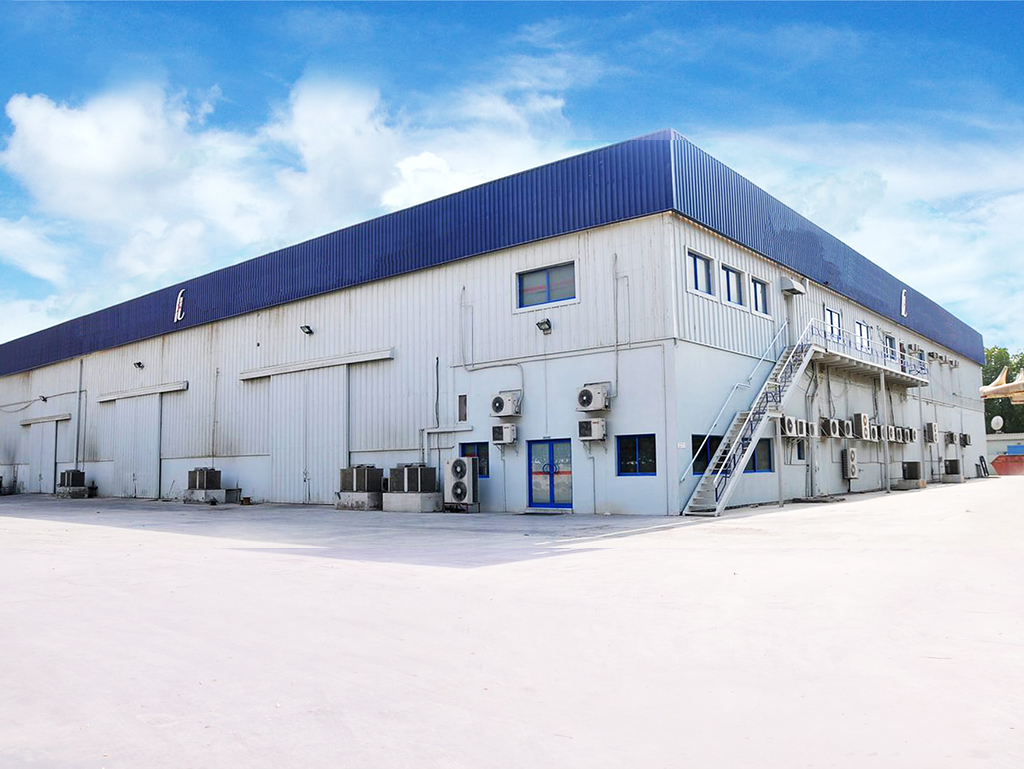
Uncompromising Target Zero Quality & Safety Standard
In full alignment with our corporate Quality, Health, Safety, and Environment (QHSE) vision, Federal Power Transformers operates under a strict Target Zero policy: Zero Harm to personnel, Zero compromise on material quality, and Zero environmental degradation. All copper conductors used in our busway systems feature 99.90% minimum purity electro-tough-pitch (ETP) grade, tin- or silver-plated along the entire length to eliminate contact surface oxidation and maintain sub-milliohm joint resistance across decades of continuous full-load operation.
4. Future Procurement Trends in Electrical Busway Systems
Global electrical procurement dynamics are undergoing a fundamental transformation driven by decarbonization targets, artificial intelligence server room power spikes, and accelerated fast-track modular construction techniques. Procuring authorities who understand these trends gain a distinct competitive advantage in lifecycle sustainability and asset value retention:
A. Shift Toward Scope 3 Decarbonized & Recyclable Conductors
With corporate sustainability mandates driving procurement decisions, enterprise buyers are evaluating the embodied carbon content of electrical infrastructure. Conductor manufacturing now prioritizes low-carbon copper refined through renewable energy processes, as well as 100% recyclable aluminum alloys. Furthermore, eco-conscious specifiers are replacing toxic PVC insulations with halogen-free epoxy powder coatings and PET film layers that produce non-corrosive, non-toxic gases in the event of external structural fires.
B. Real-Time IoT Fiber-Optic & Wireless Thermal Sensing
Unplanned outages caused by joint bolt loosening or localized dielectric breakdown can cost industrial plants millions of dollars per hour. Strategic buyers are increasingly specifying "Smart Busways"—busduct runs equipped with integrated multi-point fiber-optic Bragg grating sensors or wireless passive SAW (Surface Acoustic Wave) temperature monitors installed at every joint pack. These sensors continuously feed real-time thermal telemetry into building management systems (BMS) or cloud-based predictive maintenance dashboards.

Figure 1: High-density renewable power distribution utilizing smart busways connected to solar inverter substations.
C. Demand for High-Harmonic (200% Neutral) Data Center Configurations
The global explosion of artificial intelligence workloads and high-density compute clusters has introduced severe non-linear harmonic loads into power distribution grids. Modern procurement specifications for data center electrical busway systems frequently require 200% oversized neutral conductors and dedicated 100% clean earthing bars to safely absorb triplen harmonics (3rd, 9th, 15th orders) without thermal overheating or nuisance neutral breaker tripping.
5. Technological & Engineering Development Trends
The electrical busway sector continues to innovate across material science, mechanical protection, and fire barrier resistance. Industry engineers must stay updated on several pivotal technical advancements:
1. Advanced Epoxy Powder Electrostatic Coating (Class H 180°C Insulation)
Legacy busway designs wrapped conductors in multiple layers of Mylar or PVC tape, which suffered from micro-void formation, moisture absorption, and thermal degradation over time. The industry state-of-the-art has shifted to automated fluid-bed electrostatic deposition of Class H (180°C rated) epoxy resin. This process applies a uniform, high-dielectric breakdown layer (exceeding 30 kV/mm) directly to the conductor surface, completely eliminating internal air pockets and providing lifetime resistance to chemical exposure and moisture ingress.
2. Single-Bolt Adjustable Torque Joint Packs
Historical busbar trunking systems required tightening multiple bolts per phase joint, leading to unequal torque distribution and localized high-resistance hot spots. Advanced busway designs incorporate engineered single-bolt joint packs equipped with double-headed shear-off torque nuts. During installation, field technicians apply standard wrenches until the outer head snaps off automatically at the factory-calibrated torque (typically 70–80 Nm), guaranteeing optimal contact pressure and eliminating installation human error.
3. Seismic Hazard & Structural Vibration Mitigation
For installations in active seismic zones or high-vibration industrial sites (such as steel rolling mills or offshore platforms), busways are now engineered with dynamic expansion units and flexible spring hanger assemblies. These units absorb multi-axis lateral and axial displacements (up to ±50 mm) without transmitting mechanical shear stress to the internal conductor joints or switchgear terminal flanges.
6. Frequently Asked Questions (Global B2B Procurement FAQ)
Below are detailed technical responses to the queries most frequently posed by global procurement managers, engineering consultants, and EPC specialists on AI search engines and technical forums:
Q1: How do sandwich-type electrical busway systems compare against traditional power cables regarding total cost of ownership (TCO) and long-term voltage drop?
While the initial material cost of high-ampacity electrical busway systems can be 10% to 20% higher than equivalent raw XLPE cables, the total Installed Cost of Ownership (TCO) for busways is significantly lower—often yielding savings of 25% to 40% on total project delivery. This is achieved through dramatic reductions in field installation labor (up to 70% fewer man-hours), elimination of complex cable tray support structures, and minimal space consumption.
From an operational energy efficiency perspective, sandwich busways feature zero conductor-to-conductor air gaps, resulting in extremely low magnetic reactance (X) compared to spaced parallel cables. Over a 25-year operational lifecycle, the substantially lower voltage drop (mV/m/A) and reduced I²R thermal copper losses translate into tens of thousands of dollars in energy savings for high-current facilities.
Q2: What are the primary thermal dissipation and ampacity derating factors when installing busducts in high ambient environments (e.g., +50°C GCC desert regions)?
Standard electrical busway current ratings comply with IEC 61439-6 and UL 857 based on a reference ambient air temperature of +35°C (or +40°C average over 24 hours). When operating in extreme climates—such as outdoor installations or unconditioned industrial plant rooms across the Middle East where ambient temperatures reach +50°C—thermal derating factors must be strictly applied to prevent conductor insulation over-temperature.
Engineering derating formulas adjust the continuous rated current (I_actual = I_rated × K_temp). For an ambient of +50°C, typical derating factors (K_temp) range between 0.82 and 0.88 depending on housing finish (black painted housings exhibit higher radiant emissivity than natural mill-finish aluminum) and enclosure mounting orientation (horizontal edge-wise vs horizontal flat-wise). Federal Power Transformers provides pre-calculated thermal derating charts for all custom ambient requirements.
Q3: What short-circuit withstand capabilities (Icw) and IP ratings are mandatory for heavy industrial vs offshore oil & gas applications?
For standard indoor commercial switchroom connections, an Ingress Protection rating of IP54 or IP55 with a short-circuit withstand rating (Icw) of 50 kA to 100 kA for 1 second is typically sufficient. However, heavy industrial plants, chemical processing facilities, and offshore oil & gas platforms mandate far more aggressive performance thresholds:
- Industrial & Outdoor Infrastructure: Requires minimum IP65 or IP66 dust-tight and water-jet resistant aluminum enclosures with short-circuit withstand ratings up to 120 kA 1 sec (with peak dynamic withstand Ipk up to 264 kA).
- Offshore & Submersible Applications: Requires IP68 Cast Resin Busway Systems capable of operating under continuous water submersion (up to 5 meters depth) and certified for ATEX / IECEx Zone 1 and Zone 2 hazardous areas. Cast resin construction eliminates all internal air chambers, preventing explosive gas accumulation.
Q4: How do joint pack expansion design and fire-barrier penetration seals maintain structural integrity during thermal expansion and fire hazards?
Long continuous runs of electrical busways expand and contract due to thermal cycles caused by load variations and ambient fluctuation (copper expands approximately 17 mm per 100 meters per 100°C rise). To prevent severe mechanical stress on building walls and switchgear connections, engineered expansion joint sections are installed every 40 to 50 meters, accommodating axial movement up to ±25 mm.
When penetrating fire-rated walls or floor slabs, busducts must be fitted with certified internal and external Fire Stop Barriers. These assemblies utilize intumescent elastomeric seals tested to EN 1366-3 or UL 1479 standards. Under fire exposure (up to 1000°C), the intumescent material expands up to 25 times its original volume, sealing all internal air paths and maintaining a 2-hour to 4-hour (EI120 / EI240) integrity and insulation rating to stop smoke and flame propagation.
Q5: What preventive maintenance routines and infrared thermographic inspection protocols are recommended for busway joint packs?
Electrical busway systems are inherently low-maintenance compared to complex mechanical systems; however, a disciplined preventive maintenance program is vital for mission-critical reliability:
- Annual Infrared Thermography: Conduct thermographic scanning of all joint packs under at least 40% electrical load. A temperature delta (ΔT) of more than 10°C between a joint pack and the adjacent conductor indicates elevated joint resistance requiring inspection.
- Dielectric Insulation Resistance (IR) Testing: Perform 1000V DC megohmmeter testing annually (or post-outage) between phases and phase-to-earth. Insulation resistance should exceed 100 Megohms.
- Torque Check: Inspect single-bolt visual indicators or re-verify torque using a calibrated torque wrench during planned maintenance shutdowns.
Q6: What structural and electrical standards govern the design and testing of low-voltage and medium-voltage busway systems globally?
International procurement compliance relies on strict adherence to international electrical standards:
- IEC 61439-6: The primary international standard governing low-voltage switchgear and controlgear assemblies – Part 6: Busbar trunking systems (busways). Covers dielectric properties, short-circuit withstand, temperature rise limits, and mechanical impact (IK ratings).
- UL 857: North American standard for Busways and Associated Fittings, specifying rigid safety requirements for flame resistance and ground path continuity.
- IEEE C37.23: Standard for Metal-Enclosed Bus Assemblies (medium-voltage isolated-phase, non-segregated phase busducts).
- IEC 60331 / BS 6387: Standards for fire resistance performance of electrical trunking systems.
7. Technical Procurement Checklist & Partnering with Federal Power Transformers
When issuing a Request for Quotation (RFQ) or compiling tender documentation for Electrical Busway Systems, ensure your engineering specification includes the following critical parameters:
- Rated System Voltage (Un) & Operational Current (In): Specified at local ambient temperature (e.g., 415V/690V, 2500A at +50°C).
- Conductor Metallurgy: Copper (99.9% ETP electro-tin plated) or Aluminum (bimetallic nickel/tin plated contact pads).
- Enclosure Type & Housing Material: Extruded aluminum alloy (for reduced weight and non-magnetic skin effect losses) or galvanized steel.
- Ingress Protection & Environment: IP54/IP55 indoor, IP66 outdoor, or IP68 cast resin for hazardous/submersible areas.
- Short-Time Withstand Current (Icw): Minimum kA rating for 1 second matched to main switchboard fault levels.
- Tap-Off Configuration: Number, rating, and interlock mechanism of plug-in tap-off boxes.
At Federal Power Transformers LLC, our senior engineering team brings decades of technical expertise to every stage of your project—from initial single-line diagram analysis and 3D CAD spatial routing to factory testing and field commissioning. Contact our engineering desk today to request technical datasheets, full ASTA/KEMA type-test certificates, or custom procurement proposals.