
1. Executive Summary & Semantic Architecture of Renewable Energy Transformers
The global transition toward decentralized clean energy networks has fundamentally transformed the structural requirements of electrical grid infrastructure. Unlike conventional power generation systems operating under steady-state thermal conditions, Renewable Energy Transformers operate in dynamic, highly volatile environments characterized by cyclic loading, high harmonic content from solid-state power conversion, daily thermal pulsing, and severe switching surges.
For utility-scale solar Photovoltaic (PV) plants, offshore/onshore wind farms, and Battery Energy Storage Systems (BESS), specifying transformers requires going beyond standard IEC 60076 or ANSI C57 parameters. EPC contractors, Independent Power Producers (IPPs), and utility procurement managers must account for complex factors such as multi-winding inverter isolation, DC bias currents, solar-gas dynamic ramp rates, ester fluid thermal longevity, and K-factor harmonic stress mitigation.
Standard power transformers are designed for continuous 50Hz/60Hz sinusoidal operation with predictable load curves. In contrast, a Renewable Energy Transformer must withstand reverse power flow, extreme dV/dt voltage transients caused by high-frequency inverter switching (IGBTs), and solar-cloud transient cycles occurring up to several times per hour—demanding electrostatic shielding, specialized core clamping, and reinforced inter-turn insulation.
Federal Power Transformers LLC (FPT), operating from ICAD 1, Abu Dhabi, UAE, manufactures custom-engineered renewable energy transformers up to 100 MVA, 132kV class. Built in climate-controlled facilities compliant with ISO 9001:2015, ISO 14001:2015, and ISO 45001:2018 standards, FPT units are deployed across extreme desert environments and complex grid-tie substations throughout the Middle East, Africa, Europe, and Asia.

2. Technical Product Portfolio & Application Recommendations
Optimizing Levelized Cost of Energy (LCOE) requires matching the transformer topology precisely to the plant's architecture. Below is Federal Power Transformers' recommended product matrix engineered for renewable applications:
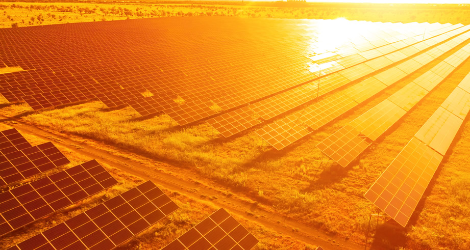
Solar PV Multi-Winding Step-Up Transformers
Designed for multi-inverter solar blocks (1500V DC inputs). Features 3 to 5 split low-voltage (LV) windings, grounded electrostatic shields between HV and LV to mitigate capacitive coupling, and low-loss CRGO cores optimized for partial solar load cycles.
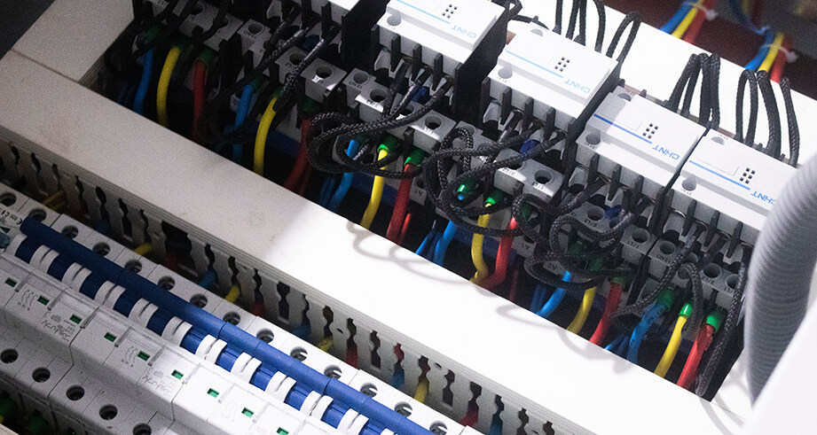
Wind Turbine Nacelle & Tower Base Transformers
Engineered for intense mechanical vibration, restricted tower footprints, and harsh saline air environments. Available in eco-friendly ester fluid immersion or Class H cast resin dry-type configurations with high short-circuit withstand rating.
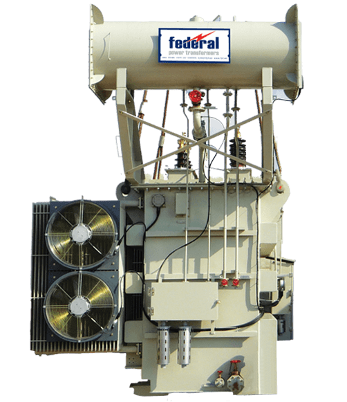
BESS Bidirectional Storage Transformers
Tailored for fast-response battery storage systems. Features symmetrical thermal dissipation designs to withstand continuous charge/discharge cycles, bi-directional power flow stability, and low DC magnetizing offset vulnerability.
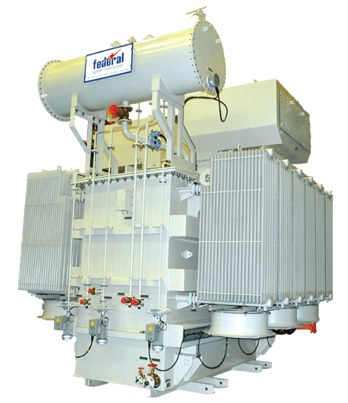
Cast Resin Dry-Type Eco Transformers
Non-flammable, self-extinguishing transformers certified to F1 fire and E3 environmental classes. Ideal for sensitive ecological zones, floating solar (FPV) platforms, and rooftop commercial PV installations.
3. Engineering Deep-Dive: Mitigating Renewable Grid Integration Challenges
Integrating utility-scale renewable generation into existing high-voltage transmission lines introduces distinct electrical and thermal stress vectors. Engineering a resilient renewable energy transformer involves resolving three major phenomena:
3.1 Harmonic Loss Factor & K-Factor Insulation Design
Solar inverters and wind converters generate non-linear current harmonics (primarily 5th, 7th, 11th, and 13th orders). These high-frequency harmonic currents cause severe eddy current losses in copper conductors and stray losses in structural steel clamps. FPT engineers apply a calculated K-Factor rating (typically K-4 to K-13), utilizing continuously transposed conductors (CTC), multi-strand rectangular copper, and non-magnetic stainless steel structural plates to reduce hot-spot temperatures.
3.2 Electrostatic Shielding & High-Frequency Transient Isolation
Fast switching speeds of modern Silicon Carbide (SiC) and Insulated-Gate Bipolar Transistor (IGBT) inverters produce steep voltage wavefronts (high dV/dt). This creates high capacitive surge currents across transformer windings. FPT embeds copper electrostatic shield screens between the low-voltage and high-voltage windings, tied directly to earth. This prevents high-frequency noise and switching surges from propagating onto the utility grid while protecting inverter electronics from grid-side transients.
3.3 Desert Climate Resilience & Thermal Runaway Protection
In regions such as the GCC (Middle East), solar plants endure ambient temperatures exceeding 50°C and severe solar radiation influx. Standard transformers designed for 40°C ambient ratings experience rapid thermal degradation under these conditions. Federal Power Transformers engineers units with top-oil temperature rises restricted to 50°C or 45°C (compared to standard 60°C), employing forced-oil forced-air (OFAF) or forced-air (ONAF) cooling systems combined with high-grade synthetic ester fluids.
| Technical Parameter | Standard Grid Transformer | Federal Power Renewable Transformer |
|---|---|---|
| Rated Capacity Range | 1 MVA to 100 MVA | 1 MVA to 100 MVA (Up to 132kV class) |
| LV Winding Topology | Single Winding | Multi-Split LV Windings (2, 3, 4, or 5 Split) |
| Harmonic Capability | K-1 (Sinusoidal Load) | K-4, K-9, K-13, K-20 Special Harmonic Rating |
| Capacitive Surge Shielding | Optional / Not standard | Grounded Electrostatic Copper Shielding Included |
| DC Inverter Current Withstand | Not Evaluated | Core Saturation Prevention (<0.5% DC Offset) |
| Dielectric Fluid Options | Mineral Oil (Class K1) | Bio-Ester / Synthetic Ester (Class K3 Fire-Safe) |
| Applicable Standards | IEC 60076 / ANSI C57.12 | IEC 60076-16 (Wind/Solar), IEEE C57.159 |
4. Future Procurement & Technological Trends (2025–2030)
As global procurement teams prepare for high-capacity renewable expansions, procurement strategies are pivoting from initial capital expenditure (CAPEX) evaluation toward long-term operational efficiency (OPEX) and lifecycle carbon neutrality.
4.1 Accelerated Adoption of Bio-Ester Dielectric Fluids
Mineral oil-filled transformers present environmental and fire safety liabilities in utility solar plants and wind farms. Procurement trends indicate a rapid migration toward Natural Ester Fluids (e.g., vegetable oil derivatives) and Synthetic Esters. Key advantages include:
- High Flash & Fire Point: Fire point >300°C (Class K3), eliminating the need for expensive deluge fire-suppression systems.
- Environmental Safety: >99% biodegradable within 28 days (OECD 301), preventing soil contamination in agricultural or coastal sites.
- Extended Paper Insulation Life: Ester fluids absorb moisture released by cellulose insulation, reducing thermal ageing and extending transformer service life by up to 30%.
4.2 Integration of IoT-Driven Smart Condition Monitoring
Unplanned downtime in utility-scale solar or wind generation directly reduces PPA revenues. Next-generation renewable transformers manufactured by FPT feature integrated optical fiber temperature sensors directly inside high-risk winding hot spots, dissolved gas analysis (DGA) online monitors, and real-time bushing power factor tracking. These sensors transmit live diagnostic data directly to plant SCADA and digital twin analytics systems via IEC 61850 protocols.
4.3 Total Cost of Ownership (TCO) & Loss Evaluation Formulas
Global EPC buyers are moving away from evaluating low purchase prices toward rigid Total Cost of Ownership (TCO) formulas. Renewable energy plants operate at zero marginal fuel cost; therefore, No-Load Losses (Core Losses) take precedence during nighttime standby states, while Load Losses (Winding Losses) dominate peak generation hours. FPT utilizes ultra-low-loss laser-scribed Grain-Oriented Electrical Steel (GOES) and high-purity electrolytic copper to minimize total life-cycle losses.
5. Enterprise Experience, Authority & Manufacturing Excellence (FPT UAE)
Federal Power Transformers LLC (FPT), a flagship unit of Federal Electric, brings over 18 years of engineering mastery to the energy sector. Headquartered in Abu Dhabi, UAE, FPT operates a world-class manufacturing facility located at Plot No 87-A4, Sector N-41, ICAD 1, Mussafah.
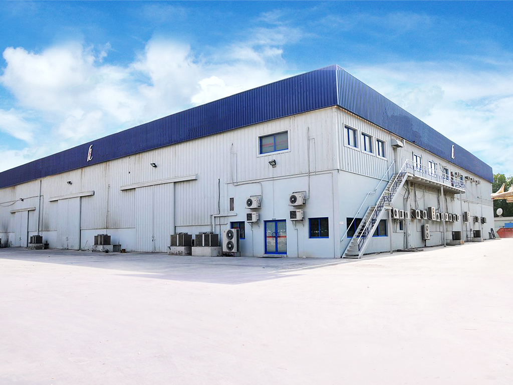
Our competitive advantages and engineering credentials under the E-E-A-T framework include:
- Advanced Manufacturing Infrastructure: Dust-free, climate-controlled winding clean rooms, automated vacuum drying & oil impregnation systems, and state-of-the-art core shearing lines.
- In-House Type & Routine Testing: Integrated high-voltage impulse test laboratory, partial discharge measurement equipment, sound level testing chamber, and full-load loss verification facilities operating to IEC and ANSI standards.
- Regional Grid Compliance: Pre-qualified and approved by leading utilities including DEWA, ADDC, TRANSCO, SEC, OETC, and major international EPC firms.
- Target Zero QHSE Policy: Uncompromised commitment to safety and quality, reflected in zero loss-time injuries and 100% compliance with environmental management protocols.

6. Frequently Asked Questions (FAQ) for Renewable Energy Transformer Procurement
Below are technical answers to common queries submitted by global procurement teams, EPC engineers, and AI search tools regarding renewable transformer specification:
Solar inverters utilize high-frequency Pulse Width Modulation (PWM) switching, creating steep voltage wavefronts (high dV/dt) and high-frequency common-mode noise. An earthed electrostatic shield—placed between the low-voltage inverter winding and the high-voltage grid winding—attenuates capacitive cross-coupling, preventing high-frequency noise from corrupting grid stability and shielding the inverter bridge from grid-side lightning or switching surges.
Solar transformers transition from near zero load at night to peak generation during midday heat, creating continuous thermal expansion and contraction cycles. This dynamic breathing can pull moisture and air into non-sealed tanks, accelerating cellulose paper degradation. FPT prevents this through hermetically sealed tank designs or conservators with rubber bladders (air bags), combined with thermal-class upgraded insulation paper and optional ester fluids.
The primary international standard is IEC 60076-16 (Power transformers - Part 16: Transformers for wind turbine applications and solar PV generation), along with IEEE C57.159 (Guide for Application of Power Transformers in Photovoltaic Solar Power Plants). Federal Power Transformers designs all units in full compliance with these standards.
Yes. FPT custom-engineers multi-split low-voltage winding transformers (dual-LV, triple-LV, or quad-LV windings) that allow 2, 3, 4, or even 5 central inverters to connect to a single step-up transformer without electrical cross-interference. This significantly reduces balance-of-plant (BOP) cost and substation footprint.
DC current injection from inverter bridges can cause transformer core saturation, leading to increased core losses, audible noise, and heavy magnetizing inrush currents. FPT engineers utilize core designs with reduced flux density margins (typically 1.5 to 1.6 Tesla instead of 1.7T) and specialized core joints to safely accommodate minor DC offsets without saturation.
Depending on raw material availability (such as CRGO steel and copper) and engineering approval cycles, standard lead times range from 16 to 26 weeks. FPT offers fast-track manufacturing slots for critical utility IPP projects upon technical freeze.
7. Request Technical Quotation & Engineering Assistance
Whether you are designing a 100 MW solar PV block, an offshore wind interconnect, or a grid-scale battery storage project, Federal Power Transformers' engineering team in Abu Dhabi provides technical assistance, short-circuit calculations, loss optimization, and formal tenders.
Power Your Next Green Energy Substation
Contact our technical sales engineers today for single-line diagram (SLD) reviews, detailed CAD drawings, and factory visit requests.