
1. Chemical Engineering Foundations of Transformer Oil Filtration
Insulating oil (liquid dielectric) serves a dual critical function within oil-immersed power and distribution transformers: it acts as an electrical insulation medium and as a thermal dissipation coolant. Over extended operational lifecycles, dielectric oil is continuously exposed to thermal stresses, localized electrical discharges, atmospheric oxygen, and moisture ingress. These combined stressors catalyze chemical breakdown mechanisms, degrading the oil's dielectric withstand capabilities.
Effective Transformer Oil Filtration is not merely a routine mechanical sweeping of solid particles; it is an engineered thermodynamic and chemical separation process designed to strip dissolved water, entrained gases, particulate matter, oxidation acids, and sludge from mineral or synthetic dielectric fluids.
The Mechanism of Dielectric Breakdown Voltage (BDV) Degradation
Liquid insulating oil loses its dielectric strength primarily due to the synergistic combination of moisture (measured in ppm) and microscopic solid conductive particles (such as cellulose fibers, iron oxides, or carbon fragments). Under high electric field intensity, polar water molecules align along particle paths, forming conductive bridges between transformer windings or between windings and the ground tank. This leads to partial discharges (PD) and ultimately catastrophic dielectric breakdown.
Core Contaminants Targeted by Industrial Filtration
- Dissolved Moisture (Water): Exists in free, emulsified, and dissolved phases. Moisture reduces breakdown voltage dramatically; a moisture level increase from 10 ppm to 30 ppm can drop dielectric strength by over 60%. Furthermore, moisture accelerates cellulose paper insulation degradation (depolymerization) irreversibly.
- Dissolved Combustible & Non-Combustible Gases: Oxygen ($O_2$) accelerates oxidation; Nitrogen ($N_2$) forms micro-bubbles under temperature fluctuations; while gases like Hydrogen ($H_2$), Acetylene ($C_2H_2$), Methane ($CH_4$), and Ethylene ($C_2H_4$) indicate active fault conditions detectable via Dissolved Gas Analysis (DGA).
- Particulate Matter & Micro-Carbon: Generated by arcing in On-Load Tap Changers (OLTC), pump wear, and cellulose insulation erosion. Particles sized between 1 µm and 5 µm act as electrical field stress intensifiers.
- Oxidation By-Products & Sludge: Soluble organic acids, aldehydes, and peroxides react with metallic copper and iron surfaces to form thick, insoluble sludge. Sludge coats cooling radiators, clogging oil flow ducts and escalating transformer operating temperatures.
International Dielectric Standard Benchmarks
Global procurement teams must enforce strict post-filtration oil parameter thresholds. The table below delineates required oil quality specifications in accordance with IEC 60422 (In-service mineral insulating oils) and IEEE C57.106 guidelines for transformers rated up to 132kV and above.
| Parameter | Test Method | Unused Oil Threshold | Critical In-Service Action Limit | Post-Filtration Target (FPT Standard) |
|---|---|---|---|---|
| Breakdown Voltage (BDV) | IEC 60156 / ASTM D877 | > 70 kV | < 40 kV (for >72.5kV equipment) | ≥ 75 kV |
| Water Content | IEC 60814 (Karl Fischer) | < 10 ppm | > 30 ppm | ≤ 5 ppm to 10 ppm |
| Total Dissolved Gas (TGD) | IEC 60567 / ASTM D3612 | < 0.5% vol | > 2.0% vol | ≤ 0.1% by volume |
| Particulate Cleanliness | ISO 4406 / NAS 1638 | Class 13/11/8 | Class 19/17/14 | ISO 12/10/8 (1-micron filter) |
| Dielectric Dissipation Factor (Tan δ) | IEC 60247 at 90°C | < 0.005 | > 0.10 | ≤ 0.002 |
2. Comprehensive Transformer Oil Filtration Technology Breakdown & Systems
Selecting the optimal transformer oil treatment plant requires matching the equipment's fluid processing mechanism with the specific operational context—be it factory testing, field commissioning, emergency maintenance, or online conditioning. Federal Power Transformers LLC recommends four primary industrial filtration system architectures for global utility and industrial procurement teams.
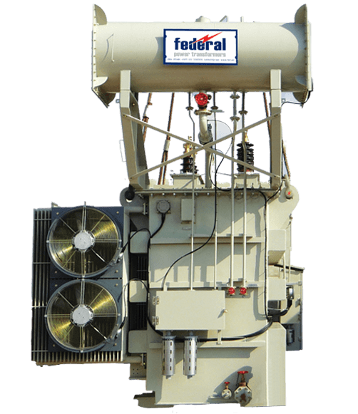
1. Double-Stage High-Vacuum Degassing & Dehydration Plants
Designed for high-voltage power transformers (≥ 132kV, up to 100 MVA). Utilizes a two-stage vacuum system combining a rotary vane backing pump with a high-capacity Roots blower. Features a multi-mesh stainless steel vacuum chamber with raschig rings or coalesce dispersers to expand oil surface area under vacuum (< 0.1 mbar).
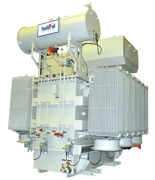
2. Thermo-Vacuum Oil Regeneration Systems (Fuller's Earth)
Integrates physical vacuum degassing with chemical adsorption columns packed with Fuller's Earth or activated alumina media. Specifically engineered for severely aged oil with high acid values (> 0.15 mg KOH/g) and deep discoloration. Reactivates media automatically in-situ via thermal oxidation cycles.
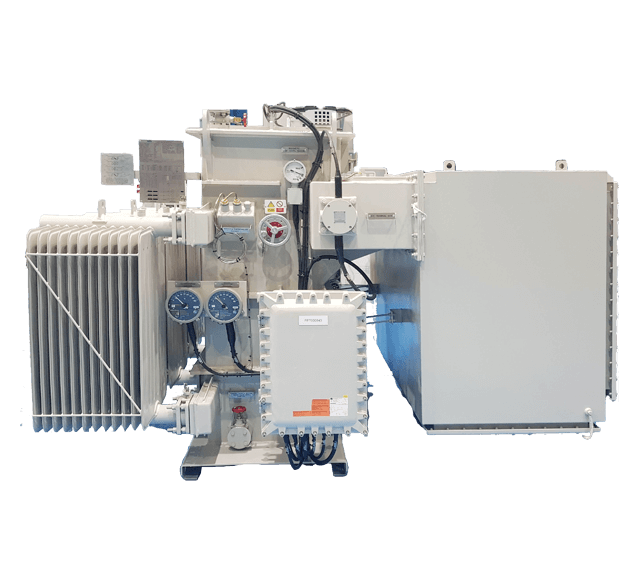
3. Online Dynamic Oil Purification Systems (Energized Operations)
Custom-engineered skid units fitted with fail-safe anti-bubble safety valves, optical bubble detectors, and precision volumetric metering pumps. Enables continuous moisture and gas extraction while the power transformer remains connected to the live grid without interruption of power supply.

4. Mobile Containerized Filtration Units for Remote Substations
Heavy-duty, weather-proof, 20ft/40ft ISO container-mounted filtration plants configured for extreme desert or offshore environments. Equipped with integrated diesel generators, oil testing laboratories, air drying systems, and remote PLC telemetry via 5G/satellite.
3. B2B Technical Decision Matrix & Procurement Guide
Procurement directors and substation asset managers frequently face the challenge of sizing and specifying filtration plants. Ordering an undersized plant extends downtime during transformer overhaul, while an oversized plant risks oil shearing and high capital expenditure.
Key Technical Specifications to Demand from OEMs
- Watt-Density Control of Electric Heaters: Insulating mineral oil deteriorates thermally if subjected to high surface watt density. Ensure that heating elements specify indirect heating or dry-element technology with a maximum heating surface watt density of ≤ 1.5 W/cm² (9.6 W/in²). High watt density causes localized carbonization and thermally degrades hydrocarbon chains.
- Vacuum Chamber Efficiency & Degassing Area: The vacuum tank must incorporate high-efficiency disperser elements (stainless steel coalesce mesh or thin-film trays). Flash evaporation efficiency relies on maximum surface film area creation at vacuums under 1 mbar at 60°C oil temperature.
- Filtration Stage Precision: Look for multi-stage progressive filtration:
- Stage 1 (Coarse Strainer): 50–100 micron stainless steel magnetic filter to trap ferrous particles and heavy debris.
- Stage 2 (Pre-Filter): 5–10 micron cartridge to protect the vacuum chamber and heater bundle.
- Stage 3 (Fine Micro-Filter): 1 micron absolute-rated (Beta ratio $\beta_1 \ge 1000$) synthetic fiber element for final dielectric polishing prior to discharge back into the transformer tank.
- Instrumentation & Automation Suite: Modern plants must incorporate inline digital moisture-in-oil sensors (measuring Water Activity $a_w$ and ppm), laser particle counters (ISO 4406), digital flow meters, and PLC control panels with SCADA / Modbus TCP connectivity.
4. Future Procurement Trends & Next-Gen Innovations (2025–2035)
As power transmission networks transition toward smart grids, renewable integration (solar PV and wind power plants), and eco-friendly infrastructure, transformer oil treatment technologies are undergoing rapid paradigm shifts. Buyers must align their long-term CAPEX strategies with these emerging industry trends.
A. Proliferation of Bio-Based Natural & Synthetic Ester Fluids
With increasing environmental regulations and fire safety requirements in urban high-rises and offshore renewable platforms, natural ester (vegetable oil) and synthetic ester fluids are replacing traditional mineral oil. However, ester fluids possess different chemical structures (higher polarity, higher viscosity, and greater water saturation limits). Next-generation filtration plants must incorporate dual-mode heating algorithms, optimized vacuum degassing pressures, and specialized filter media designed specifically to process high-viscosity ester fluids without breaking ester chains.
B. AI-Driven Predictive Maintenance & Continuous DGA Integration
Traditional periodic offline batch filtration is giving way to continuous real-time monitoring and dynamic filtration scheduling. Intelligent filtration units now connect directly to transformer asset management dashboards. Machine learning algorithms analyze DGA trends (gas generation rates), moisture ingress models, and load profiles to trigger automated filtration cycles before oil parameters breach critical IEC thresholds.
C. Zero-Emission Sustainable Mobile Filtration Platforms
Environmental, Social, and Governance (ESG) mandates are driving utilities to minimize carbon footprints during field maintenance. Future procurement specifications prioritize high-efficiency heat recovery exchangers (extracting thermal energy from treated oil to pre-heat incoming cold oil, cutting heater power consumption by up to 40%), solar-assisted auxiliary power options, and closed-loop oil recovery systems that eliminate oil spillage risks during vacuum evacuation.
D. Automated Fuller's Earth Reactivation Systems
Manual replacement and disposal of contaminated Fuller's earth filter clay represent significant hazardous waste management costs. Modern regeneration plants feature automated in-situ thermal reactivation cycles, burning off trapped contaminants inside the columns and restoring media activity for over 300 cycles before disposal is required.
Transformer Oil Filtration FAQ
Answers to critical technical queries frequently raised by grid operations directors, utility engineers, and international procurement managers.
In accordance with IEC 60422 standards, for power transformers operating above 72.5 kV, an oil dielectric breakdown voltage (BDV) dropping below 50 kV requires immediate oil filtration and reconditioning. For High Voltage and Extra High Voltage systems (220 kV to 400 kV+), the threshold is even stricter; oil BDV should ideally be maintained above 60 kV. Routine filtration restores dielectric insulation by removing suspended particles, micro-water droplets, and micro-carbon impurities.
Transformer oil purification (filtration) is a physical process focused on removing particulate solids, free/dissolved water, and dissolved gases via high-vacuum thermo-vacuum degassing. Transformer oil regeneration (reclamation) is a chemical process that uses media like Fuller's Earth or activated alumina to eliminate acidic contaminants, sludge, oxidation by-products, and polar compounds, restoring the oil's original color, interfacial tension (IFT), and neutralization value.
Yes, online transformer oil filtration is feasible under strict engineering controls. However, it requires specialized online conditioning plants equipped with automatic air-bleeding safety valves, dual bubble detectors, anti-static flow controls, and automated oil level management to prevent air bubble injection into the transformer tank, which could trigger dielectric breakdown or Buchholz relay trips.
Typically, a minimum of 3 to 5 total oil volume passes through a double-stage high-vacuum plant are required to reduce moisture content below 10 ppm and dissolved gas content below 0.1% by volume. The exact number depends on initial contamination levels, oil temperature (optimal 55°C to 65°C), vacuum depth (< 1 mbar), and flow rate relative to total tank capacity.
Transformer mineral oil is thermally sensitive. Heating elements must maintain a low watt density (maximum 1.5 W/cm² or ~9.6 W/in²) to prevent localized thermal cracking, localized oil burning, carbonization, and premature oil oxidation. Indirect electric heating or low-watt density armored heaters ensure uniform temperature elevation without damaging dielectric molecules.
Moisture distribution inside a transformer is dynamic; water migrates between oil and solid cellulose insulation depending on temperature. Cellulose paper aging is driven by hydrolysis, which accelerates exponentially with water content. By continuously drying the oil to ultra-low ppm levels via vacuum filtration, moisture is drawn out of the paper insulation into the dry oil, thereby slowing paper depolymerization and significantly extending total transformer operational life.
6. Federal Power Transformers LLC: Enterprise Advantages & Field Servicing Capabilities
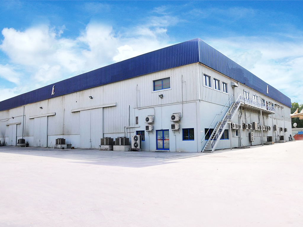
Established in 2006 in Abu Dhabi (UAE), Federal Power Transformers LLC (FPT)—a premier business unit of Federal Electric—stands as an ISO 9001:2015 certified manufacturer and total asset service provider for electrical power transmission infrastructure across the Middle East, Africa, and global international markets.

Why Global Utilities Partner with FPT for Transformer Maintenance & Filtration
- Original Equipment Manufacturer Expertise: FPT designs and manufactures power transformers up to 100 MVA, 132kV class in a state-of-the-art, climate-controlled, dust-free facility located at ICAD 1, Mussafah, Abu Dhabi. Our transformer service team possesses deep OEM knowledge regarding internal thermal hydraulics, winding insulation structures, and tap changer mechanics.
- Full-Scope Transformer Overhaul & Rewinding: Beyond field oil filtration, FPT offers complete factory repair, tap changer overhaul, active-part rewinding, core re-stacking, and high-voltage impulse testing.
- Strict Alignment with Global Standards: All manufacturing, repairing, and oil reconditioning services strictly conform to IEC-60076, ANSI C57, BS-171, and ISO 9001:2015 quality frameworks.
- Target Zero EHS Commitment: Under our core Quality, Health, Safety, and Environment (QHSE) philosophy, FPT operates under a strict "Target Zero" safety mandate—ensuring zero harm to personnel, zero oil spills, and minimum environmental impact during field filtration projects.
Optimize Your Transformer Asset Reliability Today
Need specialized Transformer Oil Filtration plants, field oil reconditioning, or technical specification support for your substation project? Speak directly with our Abu Dhabi engineering team.